Elige el adecuado, no el más caro. Este principio también se aplica ala compensación de potencia reactiva. En el proceso de compensación de potencia reactiva de la industria eléctrica, la selección de equipos de compensación de potencia reactiva de alta tensión siempre ha sido crucial. Hoy discutiremos el ámbito de aplicación de los equipos de compensación de potencia reactiva de alta tensión.
En el contexto de la compensación de potencia reactiva, la selección de un dispositivo adecuado de compensación de potencia reactiva de alta tensión es de suma importancia. Para elegir el dispositivo ideal de compensación de potencia reactiva de alta tensión, es esencial comprender su principio de funcionamiento y sus especificaciones técnicas estándar.
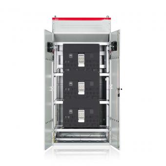
El principio de funcionamiento de banco de condensadores de compensación de potencia reactiva de alta tensión es mejorar la calidad de la energía mediante el uso de equipos de compensación de potencia reactiva, reduciendo así las pérdidas del sistema de la red eléctrica y, por lo tanto, los costos.
La compensación centralizada de alta tensión tiene tanto ventajas como desventajas. Sus ventajas incluyen una menor inversión inicial y una compensación de potencia reactiva más regular y estable debido a los picos de carga en niveles de 6–10 kV. Esto reduce significativamente el costo de aprender y utilizar equipos de compensación de potencia reactiva de alta tensión, facilitando la gestión y operación estandarizadas para las empresas. También aumenta la capacidad de carga de los transformadores, prolonga su vida útil y reduce la probabilidad de fallas. Sin embargo, sus desventajas también son significativas. Los equipos de compensación de potencia reactiva de alta tensión requieren un entorno fijo, incluido un banco de condensadores dedicado, el mantenimiento de un rango de temperatura específico y una buena ventilación. Muchas regiones carecen de entornos naturales adecuados para su uso. Además, los equipos de compensación de potencia reactiva de alta tensión solo son efectivos para la dirección de suministro de energía y el sistema de barras colectoras, no para la dirección de carga de la red eléctrica. Por lo tanto, no ofrecen muchos beneficios a los aspectos técnicos y económicos de las empresas. Sin embargo, sí mejoran el sistema de red eléctrica local, por lo que siguen siendo ampliamente utilizados por grandes empresas y
ciudades que garantizan el bienestar público.

Los equipos de compensación de potencia reactiva de alta tensión pueden compensar la potencia reactiva según el voltaje del sistema de la red eléctrica. Esto garantiza que el voltaje de la barra colectora se mantenga dentro de un rango razonable, reduciendo las pérdidas de línea y prolongando la vida útil. En particular, los contactores al vacío de los nuevos equipos de compensación de potencia reactiva de alta tensión utilizan tecnología de cierre en cruce por cero, reduciendo significativamente el impacto de la corriente de irrupción durante el cierre. Esto aumenta la tolerancia a fallos al tiempo que mejora los circuitos, evitando fallos del sistema.
Actualmente, la mayoría de los equipos de compensación de potencia reactiva de alta tensión pueden controlarse de forma remota. Para lograr operación y control remotos, es necesario supervisar diversos parámetros de los instrumentos, normalmente la secuencia de conmutación y los intervalos de tiempo. Registrar todos los parámetros: voltaje, corriente, diversos parámetros de potencia y datos de operación. La conmutación automática debe realizarse en función de las tensiones armónicas. Para una controlabilidad absoluta, también debe ser posible la conmutación manual. Solo con una supervisión suficiente de los equipos de compensación de potencia reactiva de alta tensión se puede lograr una operación continua totalmente automática.

Otros puntos complementarios:
1. Los equipos de compensación de potencia reactiva de alta tensión son adecuados para la compensación automática de potencia reactiva de barras colectoras de 6 kV y 10 kV en subestaciones de redes de distribución de 220 kV y inferiores, así como para el cambiador de tomas bajo carga en subestaciones. Logran un control integral del voltaje y la potencia reactiva de la subestación mediante el ajuste automático del cambiador de tomas bajo carga y la conmutación automática de los bancos de condensadores en la barra colectora.
2. Condiciones de uso
Temperatura ambiente: de -40 °C a +45 °C, con una temperatura media que no exceda +35 °C durante 24 horas.
Altitud: no superior a 2000 metros; para altitudes superiores a 2000 metros se deberán utilizar productos de gran altitud.
Humedad: promedio diario no superior al 95 %, promedio mensual no superior al 90 %.
Resistencia sísmica: no superior a una intensidad de terremoto de 8 grados.
Lugar de instalación: el lugar de instalación no debe contener medios explosivos, y el entorno circundante no debe contener gases que corroan metales o dañen el aislamiento, ni medios conductores, y no debe estar lleno de vapor de agua ni presentar crecimiento grave de moho.
Categorías
nuevo blog


NO.25,JINHE RD,HUAIYUAN ECONOMIC DEVELOPMENT ZONE ,BENGBU,ANHUI
Scan to WhatsApp: